Lotus Exige Data Acquisition System
Part II: Build
This is the second page in a multi-part series on and will focus on the details of building and installing all harnesses and sensors. The full series of pages is linked below:

Planning
Before any construction can begin, a plan is needed. With 20+ sensors, 100+ meters of wire required to connect them all, and many, many hours of construction time, proper planning and documentation was important.
Step 1: Requirements
Harness must be extendable. May need to add or alter sensors in the future.
Harness must be modular. Need the ability to easily replace/repair individual harnesses.
All harnesses and connections must be fully sealed and protected from the environment.
All sensor leads must be <0.5 m long for ease of replacement/maintenance.
Overall, I aimed to achieve a professional grade build quality in terms of materials in techniques. But, I opted to go for more modularity and individual connections at the expense of increased weight and failure points since this is ultimately an amateur level application and I’m the one that needs to maintain it and pay for all reworking costs.
Allocation of all I/O pins used on the C187 connection
Step 2: I/O Allocation
Besides obviously making sure that there is enough I/O on the display logger to handle all the sensors desired, I needed to plan out which specific pins would go to which harnesses and sensors.
On the C187 some analog voltage (AV) pins have a 0-15.0 V range, while others have a 0.-5.46 V range. I allocated the damper position sensors, steer angle, and brake position to the 0-5.46 V pins, as they would benefit the most from the higher resolution.
Some CAN bus pins can alternatively be used for RS-232, so I was sure to leave those unused since I didn’t need all of the available CAN buses.
I made a spreadsheet to plan all of this out, which would also serve as a source of documentation for the build.
Step 3: Layout
While the location of most sensors are generally fixed, there are decisions to be made on the harness routing to connect everything together.
I opted to have most harnesses connect to each other underneath the dash on the passenger side of the car. This kept all the cables and connectors out of sight but still accessible (somewhat, and only for small, flexible people).
I decided on having 4 separate harnesses:
Trunk: Runs from the C187 display to underneath the right side of the dash.
Front: Connects to from the trunk harness and runs through the front firewall and has termination points in each front wheel well, as well as below the windshield near the brake booster.
Rear: Connects to the trunk harness and runs through the cockpit then through the rear firewall with termination points in each wheel well, one near the bottom of the engine, and one near the top of the engine.
Driver Inputs: Connects to the trunk harness and runs underneath the left side of the dash to connect to all driver input sensors.
To determine dimensions for each harness I ran a length of higher gauge wire along the desired paths through the car and recorded all lengths and positions of splice points.
Step 4: System Diagrams
I drew diagrams for the full system layout, as well as diagrams for each individual harness documenting the lengths, splice points, and pin numbers of all connectors.


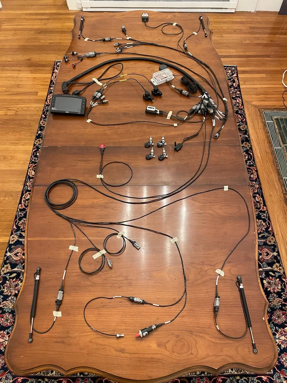
Harness Build
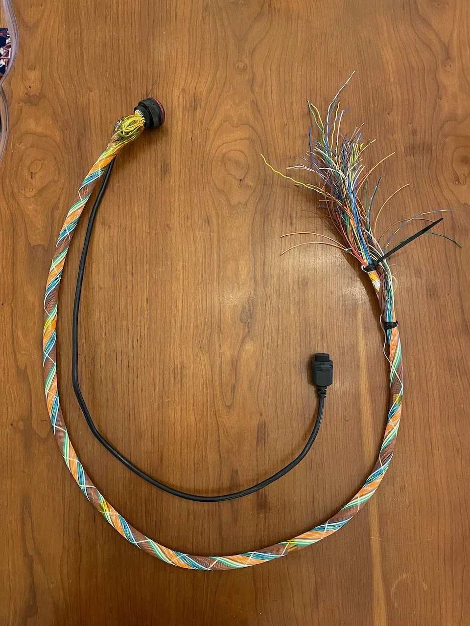
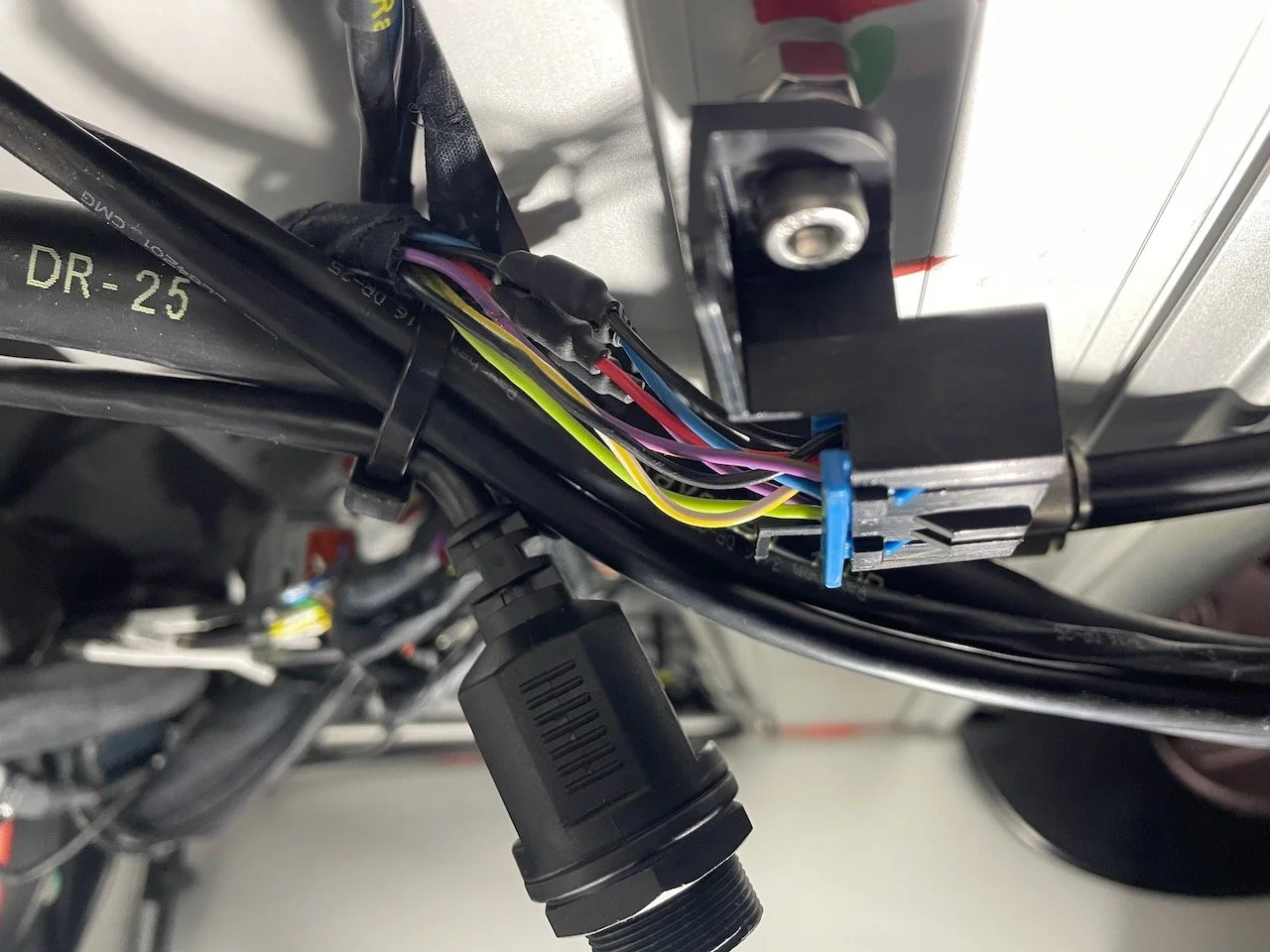
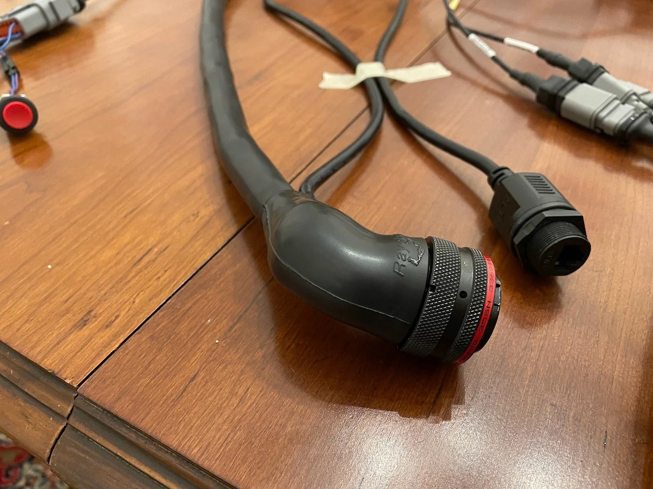
22 AWG Spec-55 wire was used throughout all harnesses. All connectors were Deutsch DTM, and these were sealed with boots made from layers of ATUM Glueline. Autosport connectors with Raychem boots are used at the highest levels of motorsports, but they have a price tag that I wasn’t willing to pay for how many connections I wanted. Finally, everything was covered with DR-25 heat shrink. Splice points were covered with a section of DR-25 as well. Again, Raychem boots with the appropriate splits would be better but they are expensive.
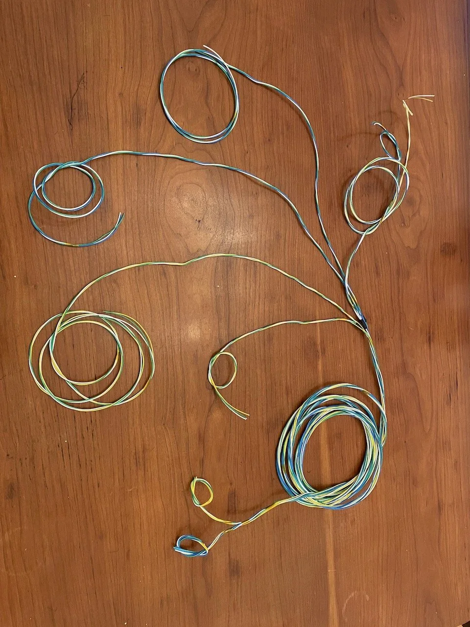
For wire colour I opted to use a simplified colouring scheme:
White: Ground
Green: Supply
Blue: Signal/RX
Yellow: TX/Other
Having just a few colours was a good balance between using a single colour throughout or having all unique colours. It made stocking up on wire feasible, while still providing enough differentiation to make labelling and the inevitable debugging straightforward compared to using a single colour throughout.
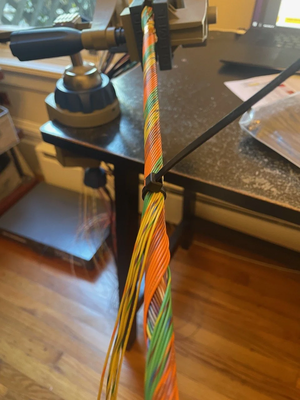
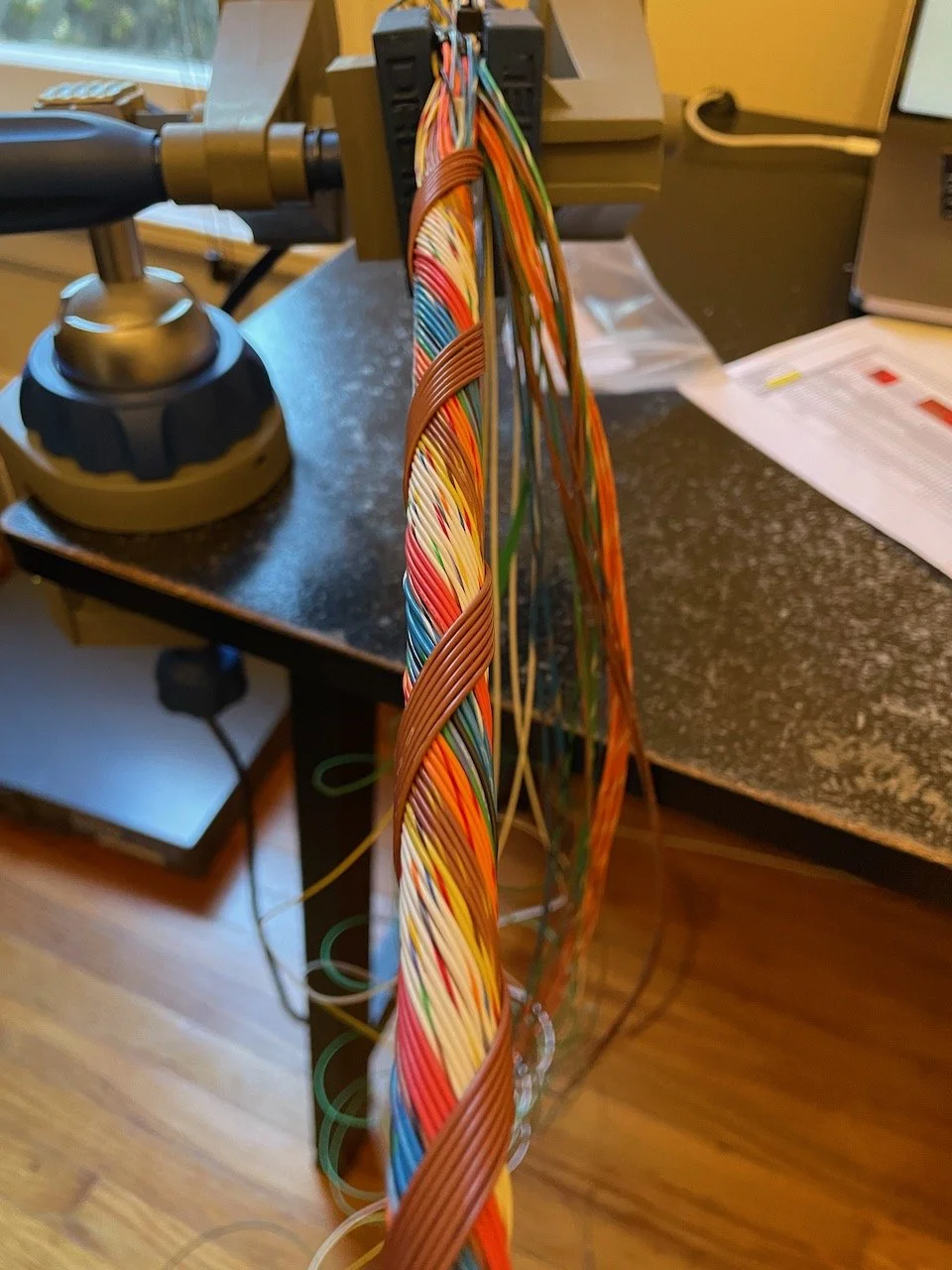
The main trunk harness running from the C187 display down to underneath the dash was concentrically wound to alleviate any stress throughout.
Tapping Into Existing Car Data
Lotus Exige’s are sparse when it comes to electronics. But, from what data was present for this model year I tried to tap into as much as I could.
The data available:
CAN: Contains engine RPM, water temperature, vehicle speed, fuel level, and MIL status
Throttle Position: This car was drive by wire, so there was already a position signal sent to the ECU
MAF Intake Temp: The MAF sensor also measures temperature and sends both signals to the ECU
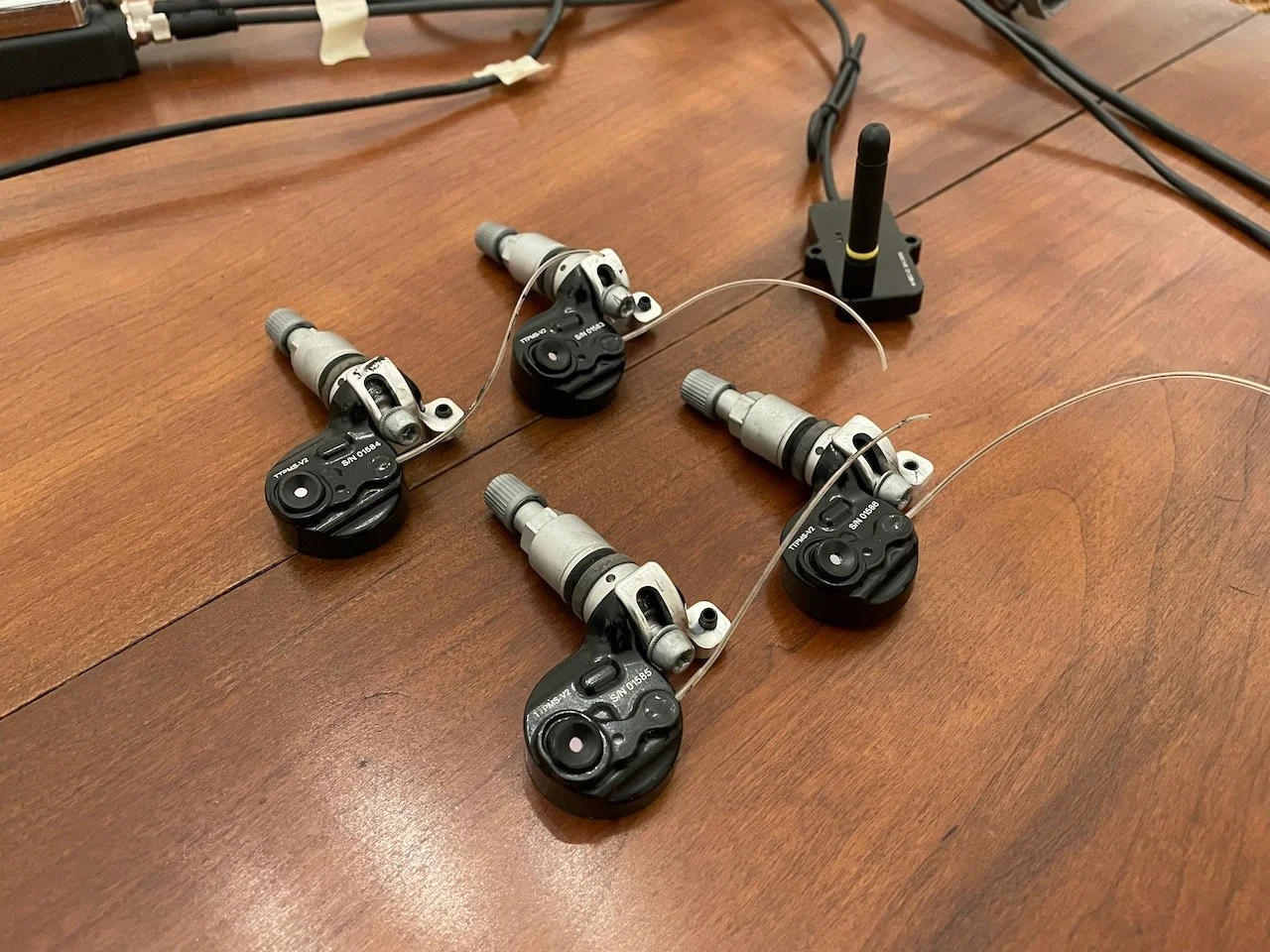
Individual Wheel Speed: Each hub as a variable reluctance speed sensor which connects to the ABS module
All existing wires that I tapped into were done by adding a parallel splice that was covered with a layer of heat shrink, then DR-25 over top of that for any splices not within the vehicle cabin.
For the CAN bus I tapped into it behind the OBD-II port since it was the most convenient location and was a short run to the main harness. For throttle position and the MAF sensor they were also both short runs to the driver input and rear harnesses.

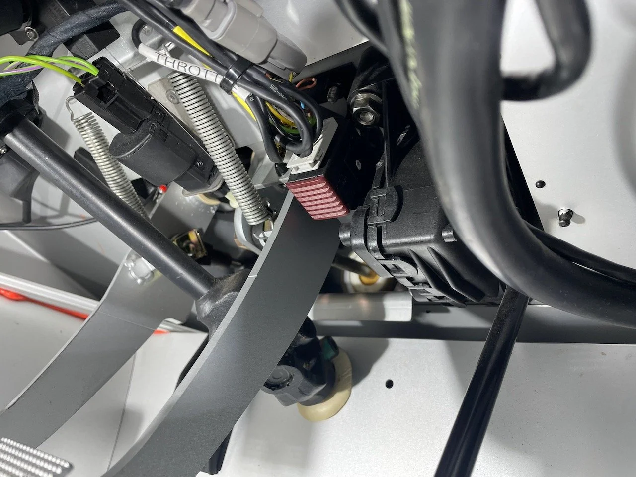
Splice added to WSS signals to intercept them before the ABS module and add a disconnect on one wheel signal
The wheel speed signals was one spot that required extra attention. These cars can have unusual ABS behaviour on a race track, so people often remove it entirely or disable the module by disconnecting the sensor on one of the front wheels. I keep my ABS disabled but I still wanted all four speed signals. Fortunately, the C187 is capable of processing outputs from variable reluctance sensors, which meant I didn’t have to rely on the ABS module to convert those to square waves.
What I did was I spliced all signals before they reached the ABS module and connected them to the C187. But, between this splice point and the ABS module I added an extra lead for one wire of the FL signal that ran through a 2-pin DTM connector that simply completed the circuit. When this was shorted, the ABS module receives all signals. When the connector is removed, the FL signal is absent, disabling ABS. All the while the C187 still gets signals from all four wheels.
Sensor Installation
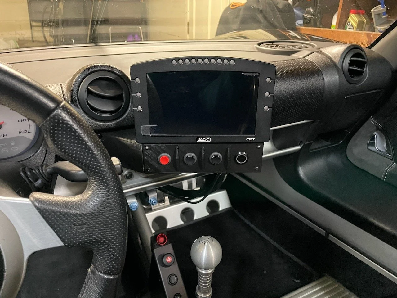
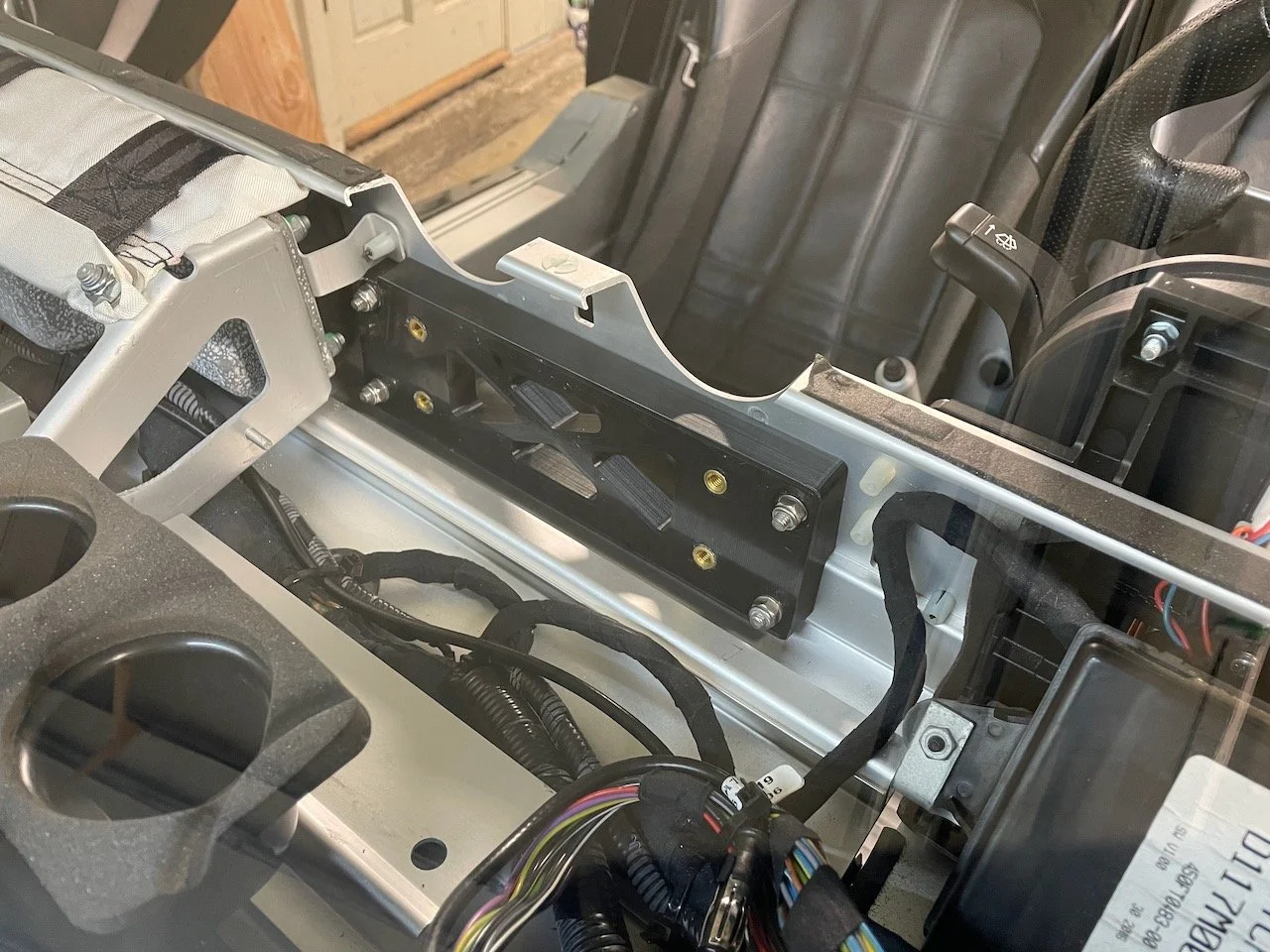
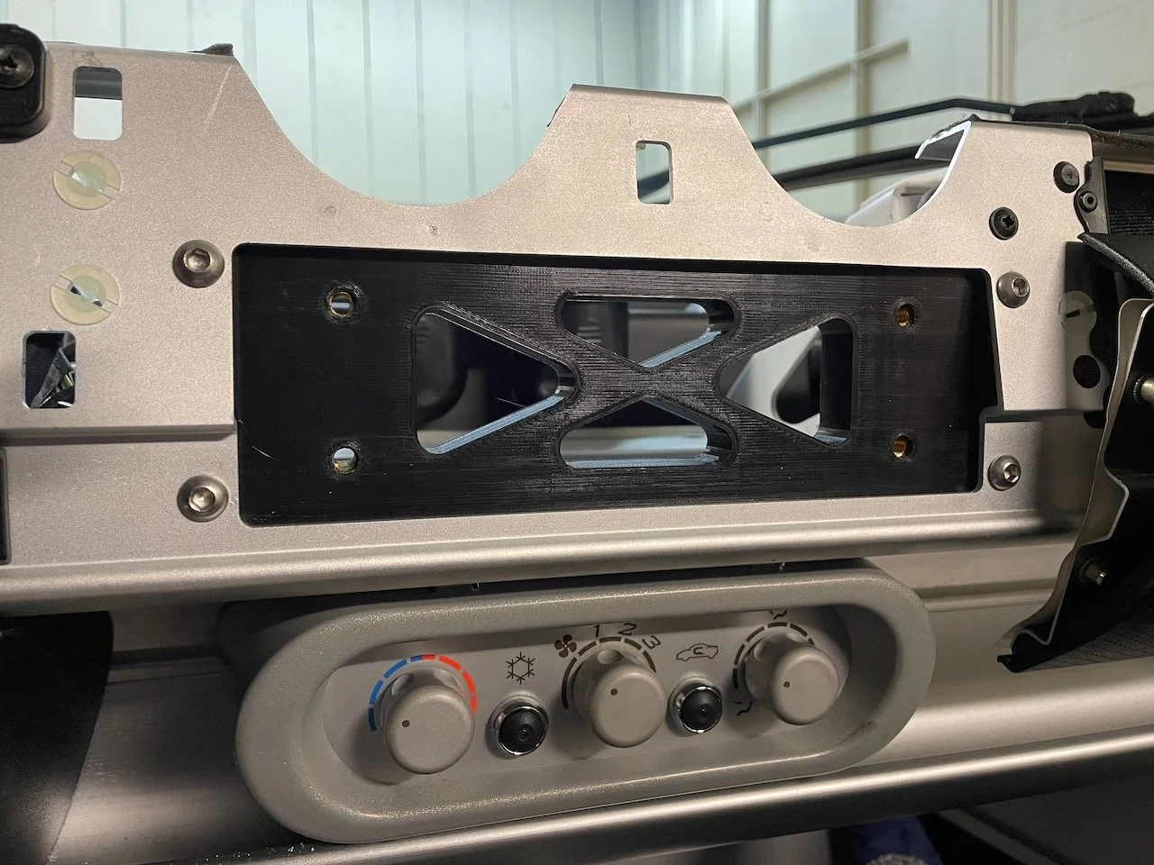
Display Mount: For the C187 display I wanted it sitting to the right of the steering wheel. Close enough that it’s always within your field of view, but far enough that your hands never occlude the screen. It also had to sit high enough to clear the shifter, but low enough to not impede your view. There’s not much room in these cars.
I was able to use the area on the dash that previously held a stereo as a mounting point. I designed and 3D printed a two piece mount that slotted right into the stereo cavity and extended out to the right position. To secure it to the dash I printed a backing plate that conformed to the dash profile that the mount could butt up against. In all printed pieces I used brass heat-press inserts to add threaded holes where they were needed.

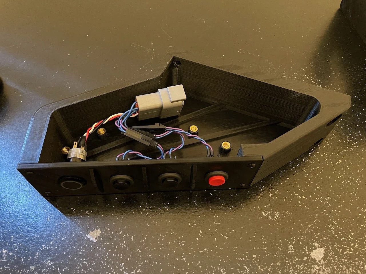


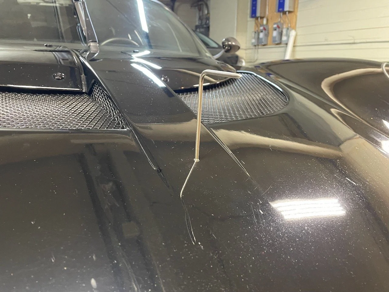
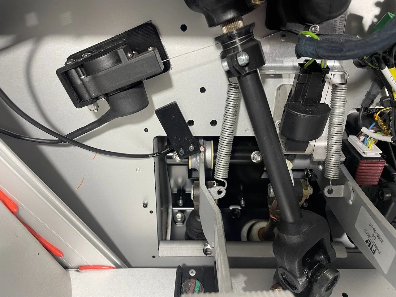
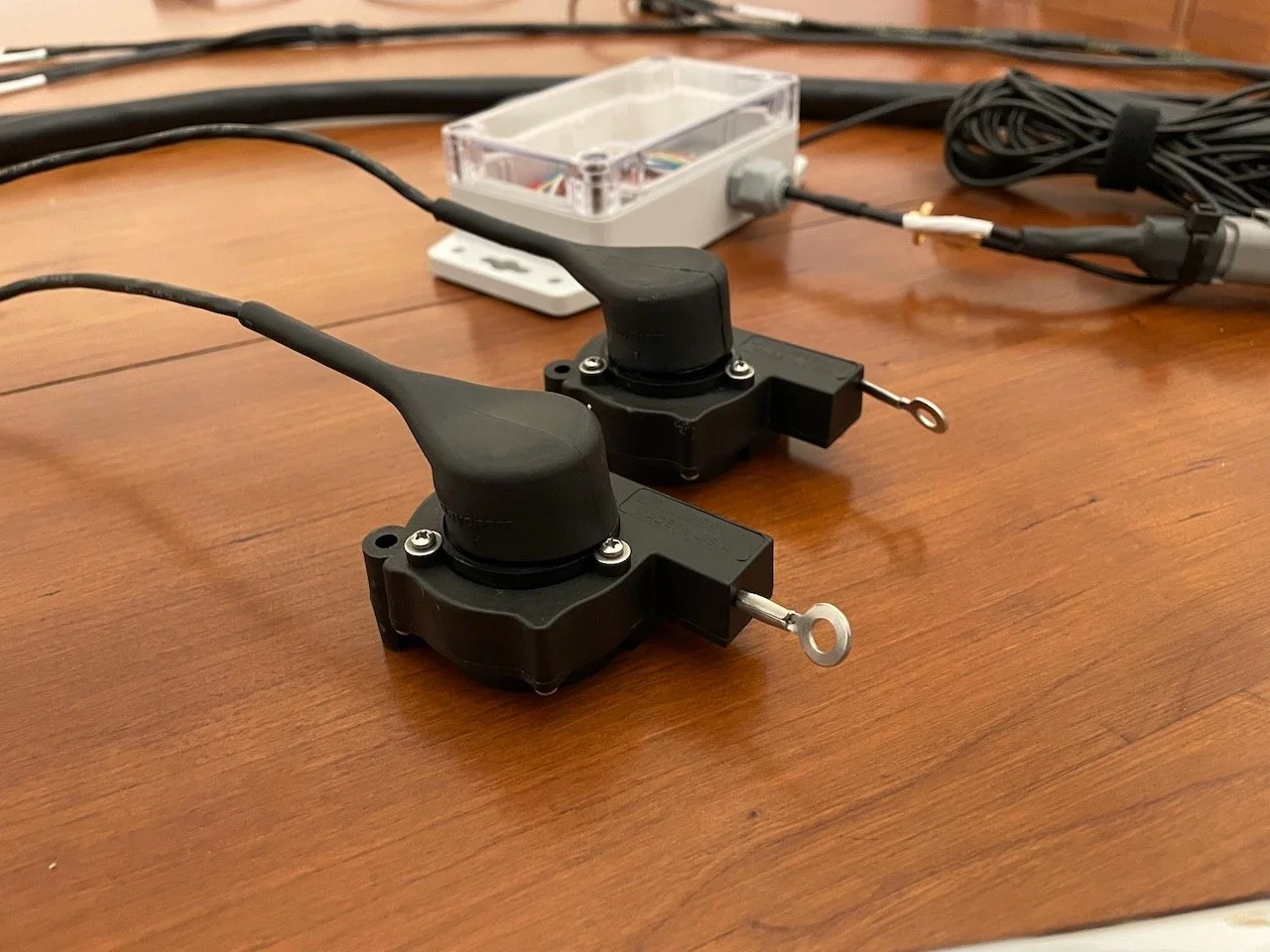
Driver Input Sensors: Mounts for the steering wheel, brake pedal, and clutch pedal position sensors were all 3D printed as well. For the steering string pot I also made a small pulley that clamps around the steering shaft for the string to wrap around.
One comment about the brake pedal string pot: This should ideally be installed such that depressing the pedal results in the string pot retracting, so that if the sensor seizes it will not restrict brake application. However, this could not be done within the tight area above the pedals without a complex pulley arrangement. Instead, the end of the potentiometer’s string is fastened with a small plastic zip-tie. One that is large enough to hold it in place, but small enough that it would break if necessary with the nominal force applied to the brake pedal under use.
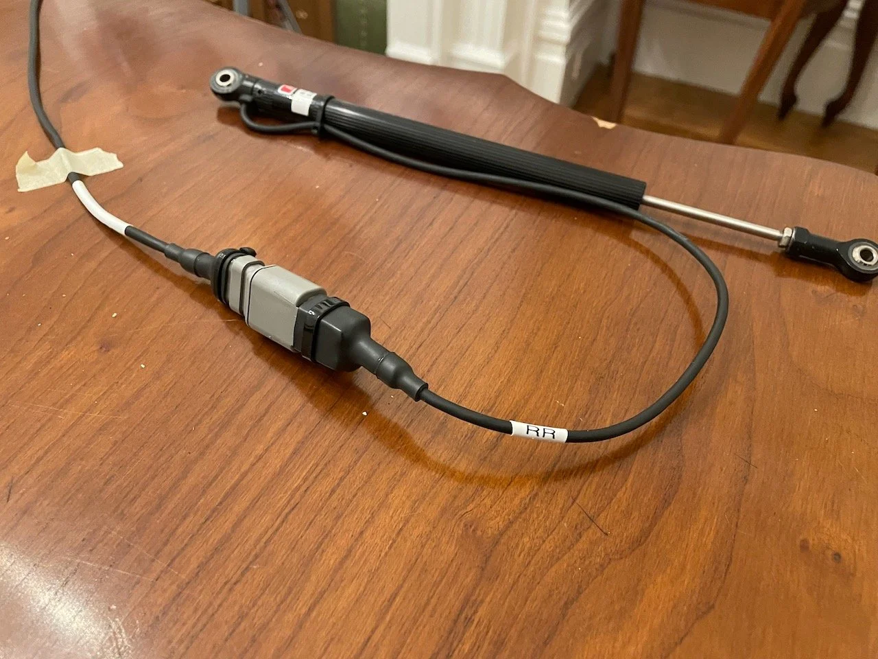
Damper Potentiometers: The damper position sensors were mounted directly beside the shocks with some simple aluminum tabs. They were kept in line with the shock shafts so that the motion ration between the shock and the sensor would be unity.
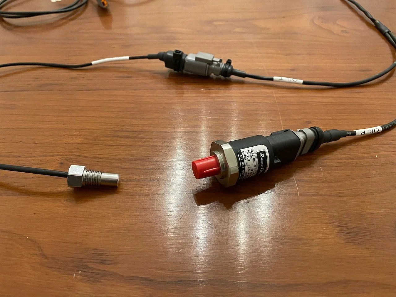
Oil Pressure: The oil pressure transducer was remotely mounted; the sensor is affixed to the firewall and connected to the sandwich plate via a short braided line. This prevents the transducer from being exposed to engine vibrations.
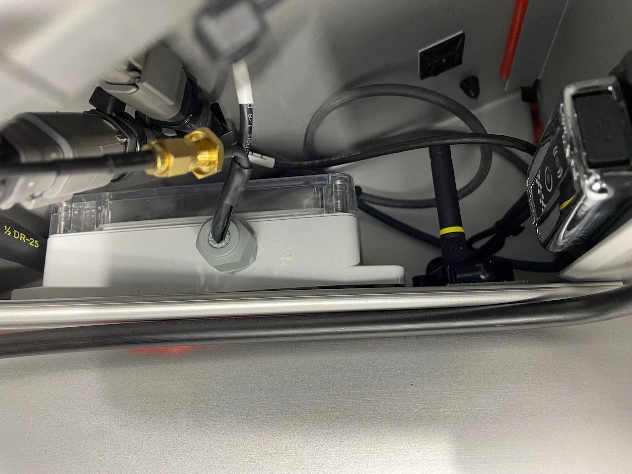
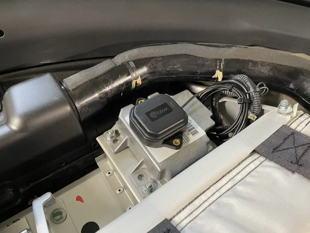
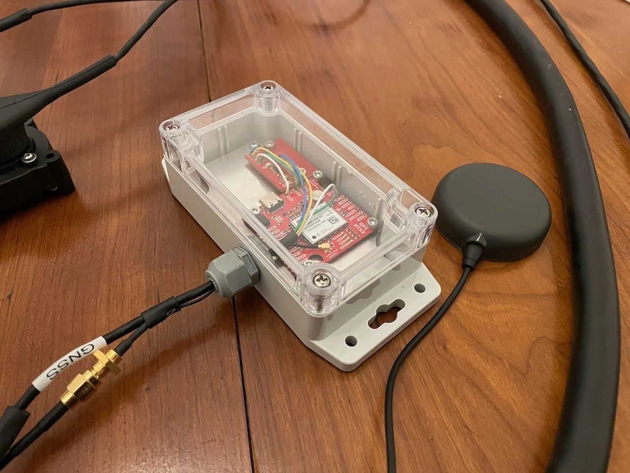
GNSS: The ublox ZED-F9P GNSS receiver I used does not have a robust enclosure, it is a development board. Also, the serial output used TTL voltage levels and not RS-232 which the C187 required. So, I had to build an enclosure for it and add in a logic level shifter to convert the output to RS-232. I used an IP65 rated case from polycase and added a sealed cable port for the board and antenna connection. While this custom arrangement is definitely more robust than a professionally manufactured sensor, I did so because I already had all of the HW necessary and I liked this particular ublox receiver. The GNSS antenna was placed underneath the top dash panel above the passenger airbag unit.
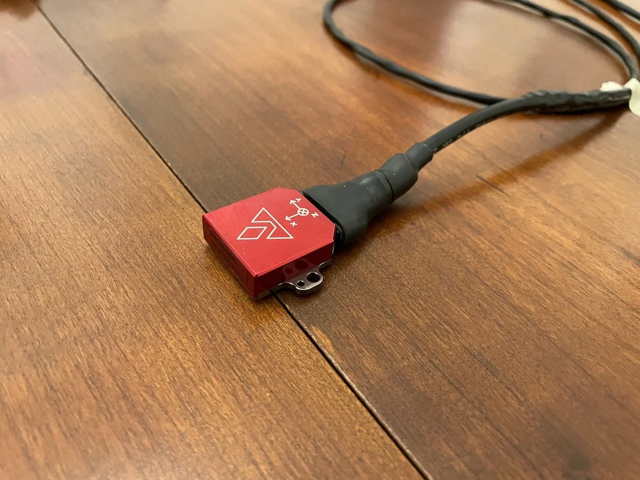
IMU: The IMU is mounted below the shifter at the centerline of the car and the midpoint of the wheelbase. It’s mounted directly to the floor with double sided tape.


Testing Process
After each individual harness was built I did a connectivity test on all pins to make sure they were wired as expected. Once that checked out the boots were heated into place and the connectors sealed.
The next step was a bench test. On a large table I laid out the MoTeC display and connected all harnesses and sensors. I built a power supply for the display that would plug into the wall to power it while testing. With the MoTeC Dash Manager software connected to the display I could inspect the outputs of all sensors. To simulate the CAN bus connection to the car I had recorded a candump on a laptop while driving, then connected my laptop to the C187’s CAN bus and replayed that CAN log to ensure the bus was working properly.
After installation there was another round of individual sensor checks before doing test drives to evaluate the whole system.

Conclusion
Overall, I was very happy with the result of the build. It looks great, I never had to rebuild anything so my planning paid off, and most importantly it works and has been issue free. There were a few spots where wire lengths or connector positions could have been adjusted or didn’t come out exactly as planned. But, nothing was so egregiously wrong that it had to be modified.
Lessons Learned:
Adding extra wires in harnesses is helpful later on when your sensing needs change. This is especially important for very long harnesses which are burdensome to rebuild and install. The front and rear harnesses had a few, but I wish I had added one or two more extra wires in the rear harness.
Connector boots result in large stiff sections adjacent to the connector, and you will have one on each side of a connection. Account for this with considering connector positions in tight areas or near bends. This is especially true when using Glueline for boots, since it is more rigid than something like Raychem boots.
DTM connectors can take up a lot of space when adjacent to each other. Factor this in when planning lengths for leads with multiple adjacent connectors.
Continue on to the next page in this series - Part III: Configuration